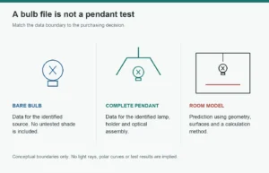
Featured image: Original conceptual diagram. Not a measured light distribution, photometric file or tested HongYu luminaire.
A supplier sends an IES file for a decorative LED bulb. Your designer imports it, places it inside a pendant model and produces a convincing restaurant lighting plan. The spreadsheet contains lux values, the rendering looks finished, and the purchasing team approves the package.
One question may still be unanswered: does the calculation represent the bare bulb, the complete pendant, or a validated optical model of both?
Those are different things. A file can import correctly and still be the wrong evidence for the product you intend to install.
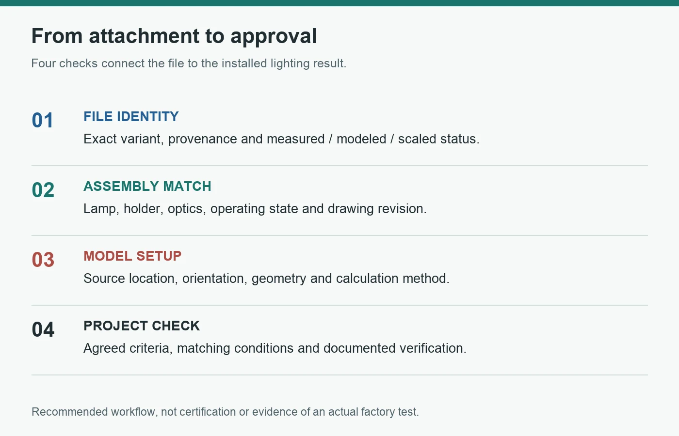
For lighting brands, importers and project buyers, the useful approval chain is file identity, tested assembly, calculation setup, then project verification. A matching wattage or a familiar bulb shape cannot replace that chain.
Start With the Object That Was Measured
The Illuminating Engineering Society describes an IES file as a standardized digital representation of the light distribution of a source or luminaire. It carries angular intensity data and identifying information for use in lighting software.[1]
The distinction between source and luminaire matters. A complete luminaire includes the lamp and the components that position, support or control its light, rather than just the replaceable bulb. DOE's definition explicitly includes optical control devices and lamp mountings.[2]
| Evidence supplied | What it can describe | What it does not establish by itself |
|---|---|---|
| Bare-bulb IES file | Distribution of the identified bulb under the stated conditions | Output from an untested shade, reflector or enclosure |
| Complete-luminaire IES file | Distribution of the tested lamp-and-fixture configuration | Performance with a different bulb, socket position or optical accessory |
| Calculated assembly model | Predicted behavior under documented modeling assumptions | A measured result for a physical production assembly |
| Product photograph or 3D model | Appearance and geometry | Verified candela distribution or installed illuminance |
For a candidate from the EU standard filament bulb range, specify the exact model, finish and operating configuration before requesting photometry. Do not accept a file merely because its name contains "G95" or "4W." Also confirm whether suitable data actually exist; a catalogue listing is not a promise that every variant has an available IES file.
Buyer judgment 1: Before approving any simulation, require one sentence identifying exactly what was measured or modeled.
A Shade Is Not Just a Decorative Outline
A shade can intercept, transmit and redirect light. Its internal finish, opening, diffuser and the lamp's position determine which parts of the bulb's output reach the room. A transparent cover is not automatically optically irrelevant either.
This does not mean every open pendant needs a new laboratory test before anyone can sketch a concept. Bare-source data can support early comparisons when the approximation is clearly stated. But as the fixture changes the light path, treating the bare bulb as the finished luminaire becomes a weaker assumption.
Consider a project moving from a clear globe to a product in the top-mirror bulb range. The reflective portion is an optical feature, not just a different color in the rendering. Its position relative to the socket, shade and target surface belongs in the assessment. The word "top" in a product name does not tell the designer which way the reflective portion faces after installation.
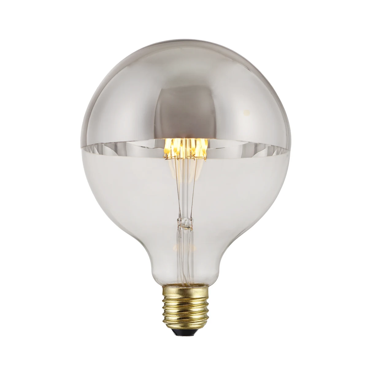
The practical question is not "Does the software show the shade?" It is "How does this calculation account for the shade's optical effect, and what validates that treatment?" A realistic-looking object is not necessarily a fully characterized optical component.
Why Total Lumens Cannot Repair the Wrong Distribution
Lumens summarize total light output. An IES distribution provides information about intensity in different directions. LightLab's description of goniophotometry explains that angular candela measurements form the distribution used in lighting calculations; those measurements can also be integrated to obtain total lumens.[3]
A simple hypothetical example shows why the distinction matters. Assume an ideal point source, a target surface perpendicular to the arriving light, a distance of 2.0 m, and no reflected-light contribution. The inverse-square relationship is E = I / d^2.[4]
| Illustrative input | Case A | Case B |
|---|---|---|
| Intensity toward the selected point | 120 cd | 60 cd |
| Source-to-point distance | 2.0 m | 2.0 m |
| Calculated direct illuminance | 30 lx | 15 lx |
| Total lumens | Not specified | Not specified |
These are invented inputs for a calculation, not HongYu test results and not an assumed 50% shade loss. They illustrate one point: the intensity toward the target matters. A total-lumen figure alone cannot supply that directional information.
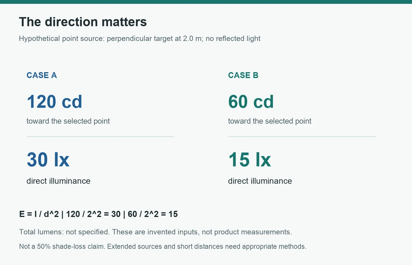
Real pendants are extended sources. At short distances, particularly around large globes and nearby shades, a point-source approximation may be inappropriate. For an oblique target, the incidence angle also matters. This example is not a substitute for a suitable calculation method or a project measurement.
Nor does multiplying every candela value by a single output factor prove that a changed diffuser, mirror cap or shade has been represented. Scaling preserves the distribution's shape. An optical change can alter that shape, not just its magnitude.
Buyer judgment 2: Do not repair a configuration mismatch by changing only the lumen value. Require evidence that the angular distribution remains applicable.
Keep the Photometric Source and the 3D Geometry Consistent
There are two defensible routes, provided their limitations are understood:
- Use complete-luminaire photometry matching the intended assembly, then configure the software's source position and representation consistently with that data.
- Build a source-plus-optics model using a suitable method, adequate source and material data, and validation appropriate to the decision.
Simply putting a bare-bulb IES object inside a decorative 3D shade does not, by itself, establish the second route. Check whether the selected calculation engine handles the relevant reflection, transmission, source geometry and near-field behavior.
Software behavior is not universal. AGi32 documents different treatment of luminaire geometry in its Full Radiosity and Direct Only methods: in one, the housing can obstruct and reflect light; in the other, luminaire symbols are not treated as calculation objects.[5] That is a reason to verify the chosen tool and method, not a claim that another program behaves identically.
For complete-luminaire data, also avoid inadvertently applying an additional optical obstruction that repeats an effect already represented in the measured distribution. Conversely, do not remove necessary external obstructions merely to make the result brighter. Ask the designer to explain what belongs to the photometric source and what belongs to the room model.
Check placement as carefully as shape. AGi32's symbol documentation distinguishes overall luminaire dimensions from the luminous dimensions used to represent the emitting region.[6] A mounting-height entry may refer to an insertion point rather than the actual light-emitting center. Record the relevant offset instead of assuming the ceiling hook, shade bottom and luminous center are interchangeable.
Buyer judgment 3: A correctly drawn fixture is not enough. Verify the source position, orientation and optical treatment used by the calculation.
Know Which Changes Reopen the Approval
Photometry should follow the approved configuration, not remain permanently attached to a catalogue family name.
| Proposed change | What the buyer should request |
|---|---|
| Clear bulb replaced with a diffusing finish | Evidence for the new output and distribution, not a renamed file |
| Reflective cap added or changed | Assessment of directional output and installed orientation |
| Socket moved deeper into the shade | Updated assembly geometry and assessment of shielding |
| Shade lining or diffuser changed | Optical reassessment using the actual material and construction |
| Lamp count or spacing changed | Updated assembly calculation; do not assume a scalar multiplier captures spatial effects |
| Operating output changed | Documented dimming/scaling assumptions and any relevant changes in distribution or appearance |
A bulb from the EU porcelain filament range may be a useful design candidate when the intended visible surface differs from exposed clear filaments. That does not make its optical data interchangeable with the clear version. Compare the actual variants and retain the approved combination in the project record.
This is also a useful manufacturing handover rule: the drawing revision, lamp variant, socket position and optical materials should identify the assembly to which the data apply. Decide who reviews changes before they reach purchasing. This is a recommended project-control practice, not a claim about an audited HongYu procedure.
Buyer judgment 4: Treat a change to the light path as a review trigger, even when wattage, base type and outer dimensions stay the same.
Ask for a Decision Package, Not Just an Attachment
Send the following checklist with the photometry request. It separates the bulb supplier's contribution from the fixture maker's and lighting designer's responsibilities.
| Deliverable | Minimum useful detail |
|---|---|
| Configuration record | Exact bulb, finish, lamp count, holder, shade, accessories and revision |
| File and provenance | Original photometric file, source, version/date and whether measured, calculated or scaled |
| Supporting evidence | Corresponding report and test-subject photograph where data are measured; assumptions and validation where modeled |
| Coordinate and output basis | Orientation, luminous dimensions, source location, operating state and any applied multipliers |
| Project calculation record | Software/method, mounting geometry, surface assumptions, calculation planes and initial or maintained basis |
| Acceptance plan | Required average/minimum illuminance and uniformity where relevant, agreed tolerances, check locations, conditions and responsible parties |
For a concept layout, provisional data may be proportionate. Label them provisional and identify which purchasing commitment depends on replacing them. Before ordering a custom pendant around a guaranteed lighting result, resolve that dependency through appropriate assembly data and verification.
In a mock-up, use the intended fixture and bulb configuration. Record mounting and measurement positions, control state, ambient-light conditions and relevant surfaces. Compare calculated and measured values on the same basis. A disagreement should prompt investigation of configuration, setup and measurement uncertainty, not an arbitrary correction factor applied until the numbers agree.
Keep appearance review separate from illuminance verification. A photograph can help approve finish and proportion, but camera exposure does not establish lux; a satisfactory lux reading does not by itself establish visual comfort, color quality, electrical safety or thermal suitability.
Buyer judgment 5: Approve the evidence for the decision being made. Concept imagery, photometric calculations and physical acceptance each answer different questions.
Conclusion
A bare-bulb IES file is useful data. The mistake is silently promoting it into proof of a complete pendant's performance.
Before approving the order, establish what the file represents, whether the assembly matches, how the model treats the optics and geometry, and how the project result will be checked. That chain is more valuable than a polished rendering built around an unidentified light source.
References
- Illuminating Engineering Society. Learn About IES Files. Back
- U.S. Department of Energy. Luminaires. Used for the definition of a complete lighting unit, not regulatory advice. Back
- LightLab International Allentown. LM-79 Intensity Measurements. Back
- Illuminating Engineering Society. Inverse-Square Law. Back
- Lighting Analysts. AGi32: Luminaire Application. Software-specific documentation; check the version and method used for the project. Back
- Lighting Analysts. AGi32: Luminaire Symbols, Concepts. Back