Dimming complaints are the single most common category of LED product return in both retail and commercial lighting channels. Flicker at low dim levels, buzzing from the dimmer, lamps that drop out before reaching minimum brightness, or lamps that will not switch off completely — all of these problems stem from the same root cause: a mismatch between the LED driver and the dimmer controlling it. This guide explains the full technical picture of LED dimming, provides a practical troubleshooting framework, and gives buyers the information they need to specify dimmable LED filament products correctly.
The Fundamentals of TRIAC Dimming
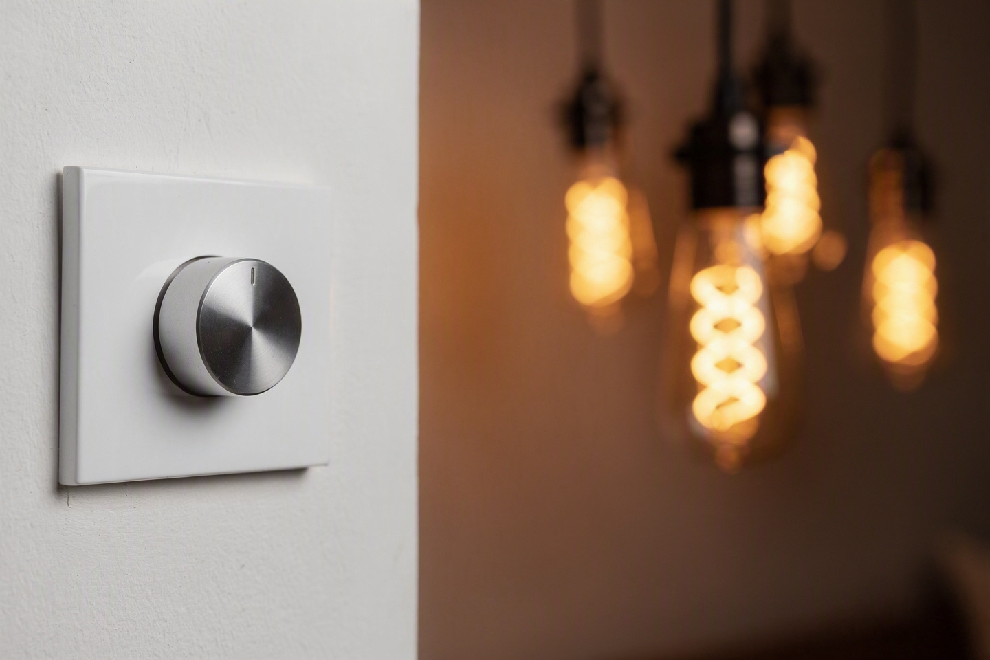
TRIAC (Triode for Alternating Current) dimming is the dominant dimming technology for residential and light commercial applications worldwide. A TRIAC dimmer works by "chopping" the AC mains waveform — blocking part of each half-cycle to reduce the average power delivered to the load. The proportion of each cycle that is blocked determines the dim level: more blocking means lower average power and lower brightness.
This chopping can occur at the beginning of each half-cycle (Leading Edge, or LE dimming, also called Forward Phase dimming) or at the end (Trailing Edge, or TE dimming, also called Reverse Phase dimming). These two types interact differently with LED drivers, and the distinction is critical to dimming performance.
Leading Edge (LE) Dimmers
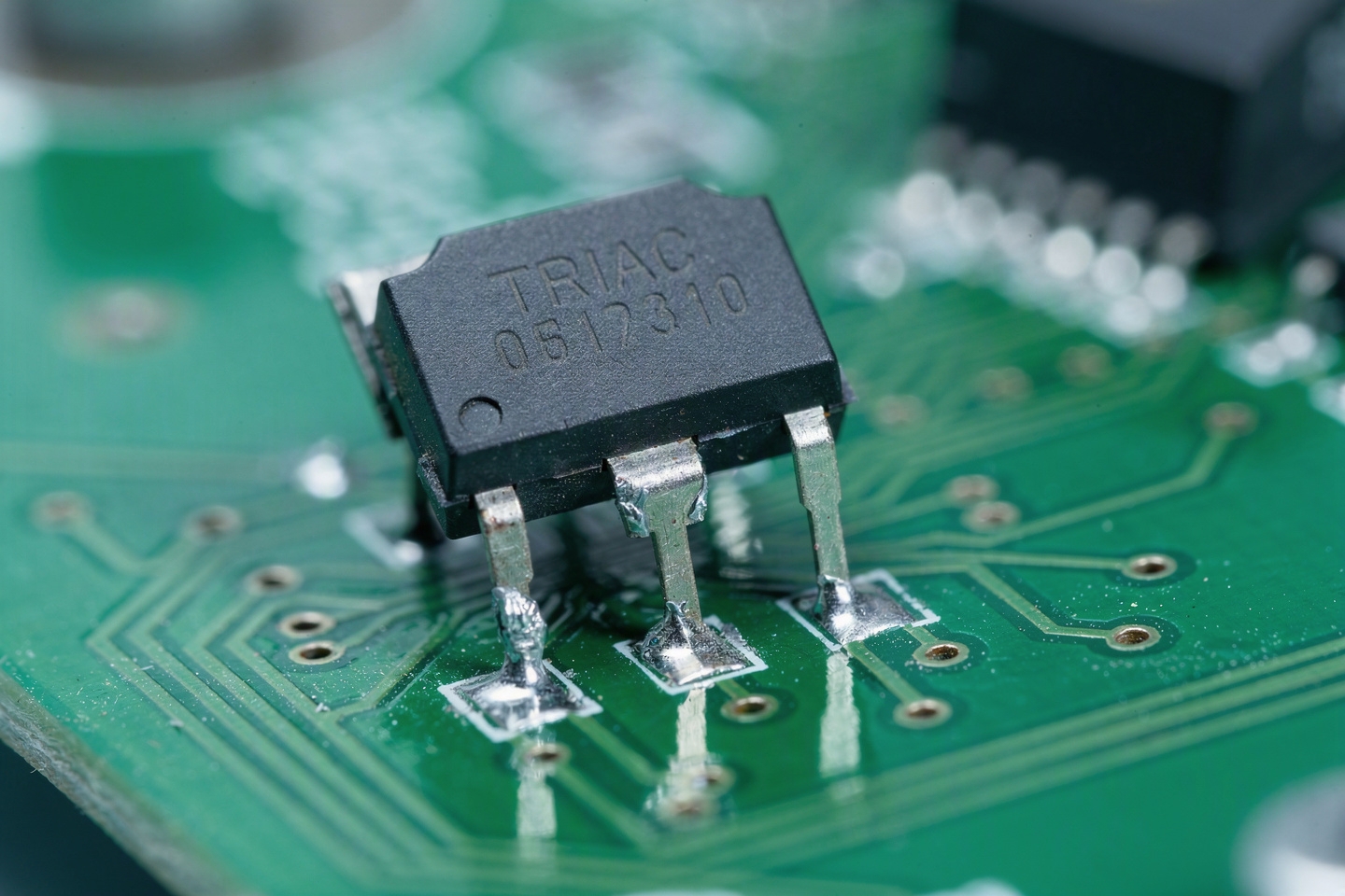
Leading Edge dimmers — also called conventional dimmers or resistive/inductive load dimmers — cut the front of each AC half-cycle. They were designed for resistive loads (incandescent filaments) and inductive loads (magnetic transformers for halogen lamps). The rapid rise in voltage at the point where the TRIAC fires can interfere with LED drivers, which often have front-end capacitors that are suddenly exposed to a near-vertical voltage step. This interference can cause audible buzzing from the driver and luminaire, and can create high-frequency current spikes that are difficult for the LED driver to handle smoothly.
Leading Edge dimmers are the most common type in existing residential installations in Europe and North America. Most were installed during the incandescent era and many are rated for minimum loads of 25–40 W — a threshold that small LED loads can struggle to meet. For LED dimming, LE dimmers work acceptably with most quality LED drivers, but trailing edge dimmers are preferred for new installations.
Trailing Edge (TE) Dimmers
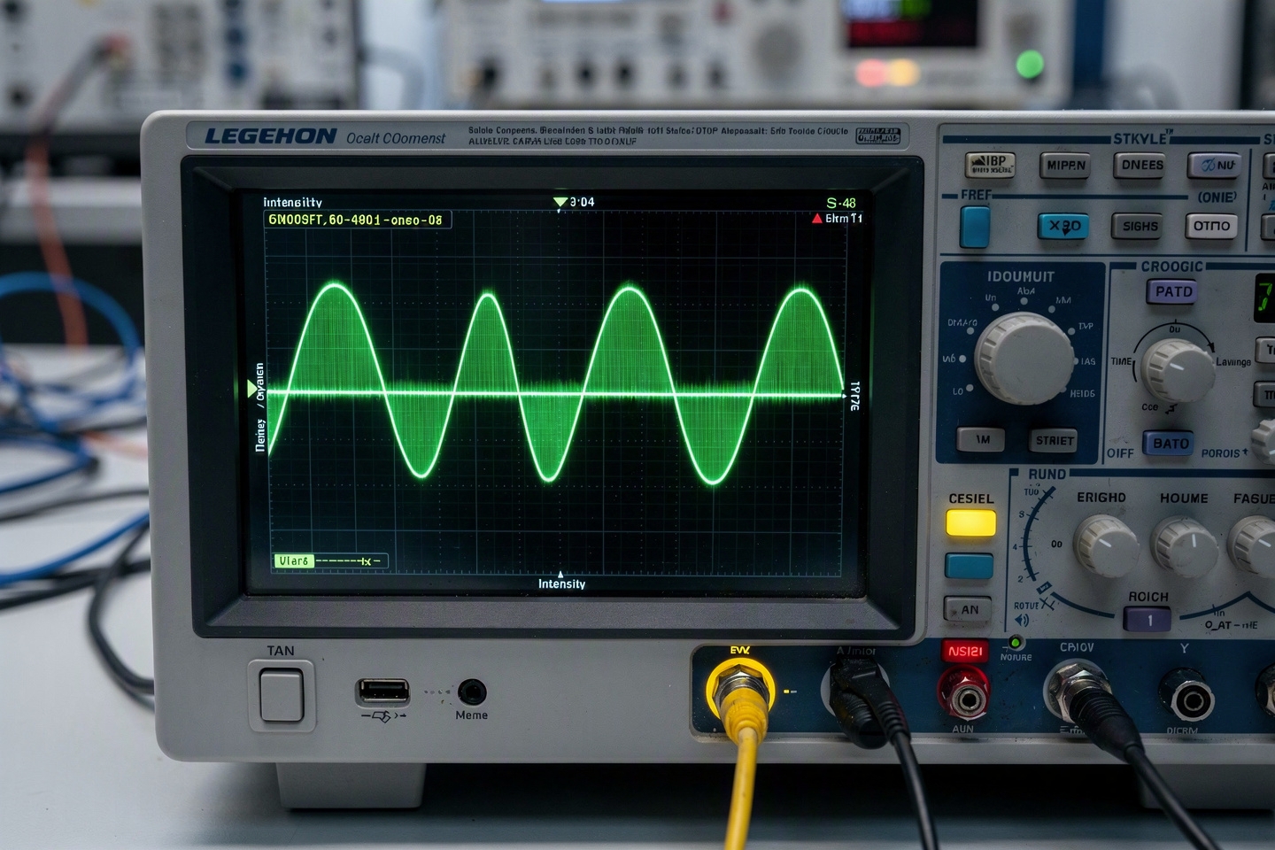
Trailing Edge dimmers cut the back of each AC half-cycle — the opposite of Leading Edge. Because the TRIAC turns off at the zero-crossing point of the waveform (where voltage is already near zero), there is no sudden voltage step. LED drivers handle this gentler waveform more easily, producing smoother dimming curves and less audible noise. Trailing Edge dimmers are specifically designed for capacitive and electronic loads, making them the technically correct choice for LED drivers.
For new construction and renovation projects, specifying trailing edge dimmers throughout is the best practice for LED filament dimmer installations. The cost premium over leading edge is modest (typically 20–40%) and the improvement in LED performance is significant.
Universal / Adaptive Dimmers
Universal or adaptive dimmers automatically detect the load type and switch between leading edge and trailing edge modes accordingly. They represent the current state of the art in residential dimmer technology and are the recommended specification for any new installation involving LED filament bulbs. Some universal dimmers also include load-specific calibration — a trimmer or menu setting that allows the installer to optimise the dimming curve for the specific LED product being used.

Understanding LED Driver Behaviour Under Dimming
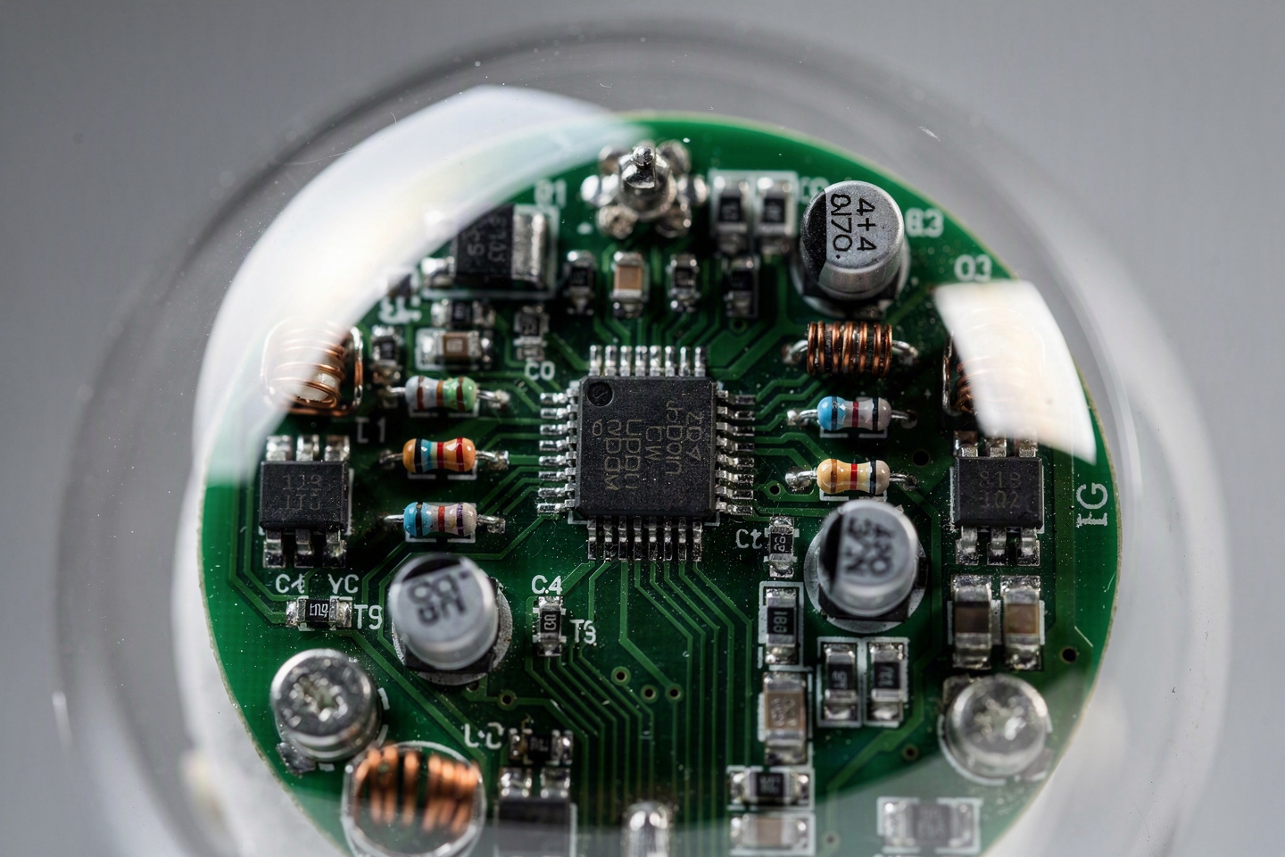
The LED driver is the critical intermediary between the mains dimmer and the LED filament chips. Its job is to interpret the chopped mains waveform as a dimming signal and respond by reducing the current delivered to the LED chips in a controlled, smooth, flicker-free manner. The sophistication of the driver's dimming algorithm determines the quality of the dimming experience.
A high-quality LED filament driver will:
- Detect the phase angle of the TRIAC signal accurately across the full range from 100% to minimum.
- Map the detected phase angle to a smooth, perceptually linear reduction in LED current — perceptual linearity is important because human vision perceives brightness on a logarithmic scale; a linear reduction in current produces a brightness curve that feels rapid at first and very slow at low levels.
- Maintain stable, flicker-free output at all dim levels, including at very low levels (5–10% output) where many drivers become unstable.
- Provide a clean "off" — the lamp should switch off completely at the minimum dimmer setting, not remain at a faint visible glow.
- Tolerate the electrical noise inherent in different TRIAC dimmer types without generating audible interference.
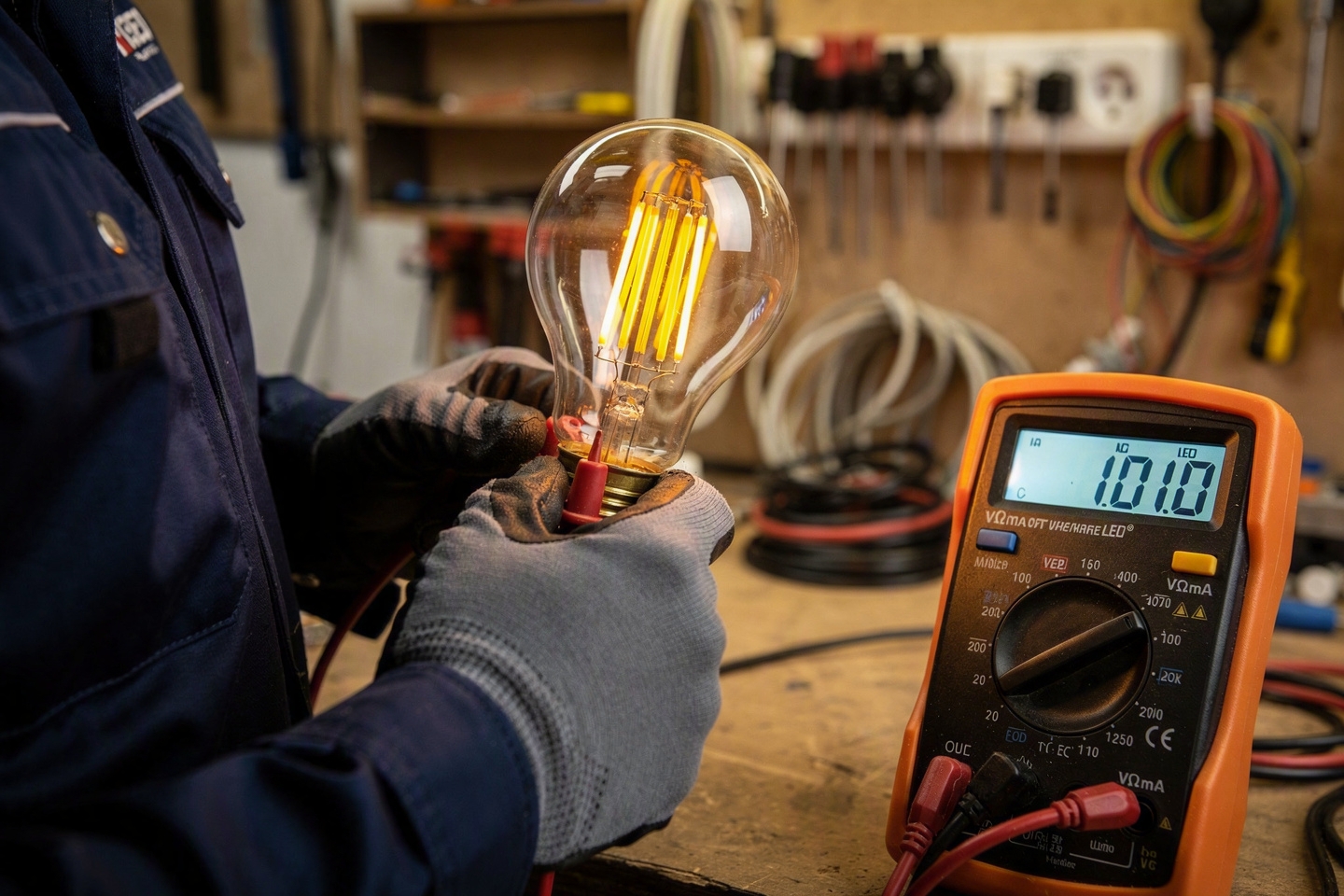
Flicker: Types, Causes, and Standards
Flicker in LED lighting is one of the most discussed and least well understood topics in the industry. Not all flicker is the same, and the standards that govern it are more nuanced than the simple "flicker-free" marketing claims on many products suggest.

Visible Flicker (3–80 Hz)
Visible flicker — where the light output appears to pulse to the naked eye — is the most obvious form and the one that generates immediate complaints. It is caused by the LED driver failing to filter the 100 Hz (or 120 Hz in the US) ripple on the rectified mains voltage that results from TRIAC phase cutting. Drivers with insufficient output capacitance or poorly tuned control loops allow this ripple to reach the LED chips directly, producing a visible pulsation at twice the mains frequency. Even at full power, low-quality drivers may exhibit some visible flicker on leading-edge dimmers — this is a clear indicator of driver quality problems.
Stroboscopic Flicker (80 Hz and above)
Flicker above approximately 80 Hz is generally not visible as a direct pulsation but can still cause problems. The stroboscopic effect — where rotating machinery appears to move in slow motion or in discrete steps — is caused by flicker in the 80–2000 Hz range. In industrial environments with rotating equipment, this is a safety concern. In retail environments, it can affect the perceived motion of merchandise displays. IEEE Standard 1789 defines a "low risk" threshold for stroboscopic flicker as a function of frequency and modulation depth.
Camera Flicker
Even high-frequency flicker that is invisible to the human eye can be detected by camera sensors with rolling shutters — including the cameras in modern smartphones. The result is banding (horizontal dark stripes) in photographs and video taken under flickering LED light. As social media and user-generated content have become ubiquitous in hospitality environments, camera-flicker compatibility has moved from a niche concern to a mainstream specification requirement. Look for "camera-friendly" or "flicker-free" specifications supported by Pstlm <1 and SVM <0.4 measurements.
Flicker Metrics Explained
| Metric | Standard | Acceptable Threshold | What It Measures |
|---|---|---|---|
| Percent Flicker | IES LM-79 | <30% at full; <10% dimmed | Amplitude of light output variation as % of average |
| Flicker Index | IES LM-79 | <0.1 | Area above average in one cycle / total area |
| Pstlm (short-term flicker) | IEC TR 61547-1 | <1.0 | Perceptual sensitivity-weighted flicker severity |
| SVM (Stroboscopic Visibility Measure) | IEC TR 61547-1 | <0.4 (low risk) | Visibility of stroboscopic effect at 80–2000 Hz |
Load Calculation: Avoiding the Minimum Load Problem
Every TRIAC dimmer has a rated wattage range — a minimum and maximum load within which it operates correctly. This range was established during the incandescent era, when a typical residential dimmer circuit might carry 200–600 W of load. Modern LED circuits carry a fraction of this. A living room circuit of eight 4 W LED filament bulbs represents just 32 W of total load — potentially below the minimum load threshold of many older dimmers.
When the total LED load falls below the dimmer's minimum, the dimmer may exhibit:
- Instability at low dim levels — the dimmer "hunts" for a stable firing angle
- Failure to turn off completely at the minimum setting
- Increased flicker due to irregular TRIAC firing
- Audible buzzing from the dimmer itself
Solutions: Replace with a modern LED-rated dimmer with low minimum load (3–5 W); add a load resistor to bring the circuit into the dimmer's operating range (wasteful, but sometimes the only option without rewiring); or reduce the number of bulbs on a single dimmer circuit.
Troubleshooting: Common Problems and Solutions
| Symptom | Most Likely Cause | Solution |
|---|---|---|
| Flicker at all dim levels | Driver quality insufficient / incompatible dimmer type | Try trailing edge dimmer; upgrade to higher-quality bulb |
| Flicker only at low levels | Total load below dimmer minimum; driver instability at low dim | Add LED load resistor; replace dimmer with LED-rated low-minimum model |
| Audible buzz from dimmer | Leading edge dimmer with capacitive LED load | Replace with trailing edge dimmer |
| Audible buzz from bulb/fixture | Driver resonance at TRIAC switching frequency | Try different dimmer brand; some driver-dimmer combinations resonate at specific frequencies |
| Won't turn off completely | Load below dimmer minimum; leakage current through dimmer | LED-rated dimmer with electronic cutoff; check dimmer specifications for LED compatibility |
| Drops out before reaching minimum | Driver protection triggering at low input voltage | Adjust dimmer low-end trim (if available); replace with different driver/bulb |
| Banding in phone camera | High-frequency flicker (camera stroboscopic effect) | Specify bulbs with SVM <0.4 and Pstlm <1 certification |
Dimmer Compatibility Testing: How to Do It Right
For large commercial or hospitality installations where the dimming experience is critical to the end-user outcome, systematic dimmer compatibility testing is worth the investment before final specification is locked in. The process:
- Step 1: Obtain samples of the LED filament bulbs and all dimmer models to be used on the project.
- Step 2: Build a test circuit with the same number of bulbs per dimmer as will be installed in the final project.
- Step 3: Test each dimmer-bulb combination across the full range from 100% to minimum. Check for flicker, buzz, dropout, and incomplete switching off at minimum.
- Step 4: Photograph the lit circuit with a smartphone camera at each dim level. Check for banding in the images.
- Step 5: Document the combinations that pass and those that fail. Specify approved combinations in the project lighting specification.
- Step 6: For prestige installations, commission professional flicker measurement (Pstlm and SVM) from a calibrated laboratory on the approved combination.
Related HongYu Bulb product pages
- LED Filament Bulb Product Range → — standard and decorative LED filament bulbs for wholesale and project sourcing.
- EU Dim-to-Warm Bulbs → — warm dimming filament bulbs for hospitality and mood lighting.
- LED Dimming Guide → — technical guidance for TRIAC dimming, flicker and compatibility.
- Contact HongYu Bulb → — send specifications, target market, quantity and packaging requirements for quotation.
Conclusion
Dimming performance is not a property of the LED bulb alone — it is an emergent property of the bulb driver, the dimmer, and the total circuit load interacting together. Specifying for dimming success requires understanding all three components and testing the complete system before deployment. The reward for getting it right is a dimming experience that delights end users and eliminates the callbacks and returns that plague LED dimmer installations where compatibility testing is skipped.
All dimmable LED filament bulbs in the HongYu Bulb range are tested for smooth TRIAC dimming compatibility, with Pstlm <1, SVM <0.4, and camera-friendly performance. Dimmer compatibility lists for major dimmer brands are available on request. Contact us for technical specifications and samples.