Your sample ST64 lamp passes photometric testing in a laboratory socket. Six months later, the same model performs differently in two customer projects.
In the first project, it stands glass-up in a table lamp. In the second, it hangs glass-down from a hotel chandelier. A third customer installs it horizontally in a wall sconce.
The voltage, wattage, CCT and carton label are identical. The thermal system is not.
That distinction is easy to miss because operating position is often treated as an installation note. For an LED filament bulb, it can change natural convection inside the glass envelope, airflow around the lamp, temperature at the cap and driver, stabilization time and sometimes measured optical or electrical performance.
The central purchasing insight is:
Operating orientation is a test condition. If the intended position is absent from the approval record, the approved product is not fully defined.
This does not mean base-up is always worse, or that every lamp changes significantly with position. It means the worst position depends on the actual lamp, fixture and environment and must be established by measurement rather than assumption.
First, Name the Three Positions Correctly
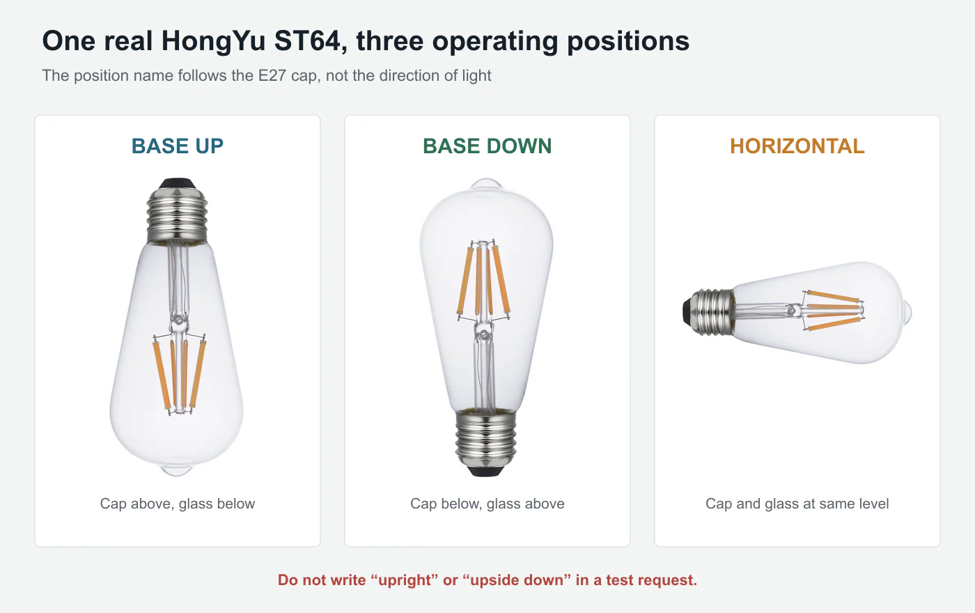
Orientation language becomes confusing when a buyer writes “upright” or “upside down.” Those descriptions can refer to the glass, the light direction or the fixture.
Use the cap as the reference:
- Base-up: the cap is above the glass envelope. A pendant or chandelier lamp hanging glass-down is base-up.
- Base-down: the cap is below the glass envelope. A bulb standing in a table or floor lamp is base-down.
- Horizontal: the cap and glass are approximately at the same height, as in many wall sconces.
If a fixture uses an angle, record the actual angle or a clear installation drawing. Do not rely on a translated adjective.
U.S. Department of Energy test-procedure work evaluated LED lamps in base-up, base-down and horizontal configurations. DOE reported that some models showed orientation-related variation in input power, lumen output, CCT and CRI, and its procedure used equal numbers of base-up and base-down samples unless the manufacturer restricted the operating position.[1]
That is a useful warning for B2B buyers: if a regulated test method records position, an informal supplier report should not omit it.
Concrete judgment 1
A test report that does not state lamp orientation is incomplete for cross-supplier or cross-project comparison.
Why Orientation Changes the Thermal Path
An LED filament lamp removes heat differently from a conventional SMD bulb with a visible aluminum heat sink.
The LED chips are distributed along narrow filament substrates inside a sealed glass envelope. Heat moves from the filaments through their coating and substrate, into the fill gas and glass, and then to the surrounding air. The compact driver is normally located in or close to the cap.
A European test program on clear non-directional LED lamps described this architecture: filament lamps use a thermally conductive gas to transfer waste heat from the filaments to the glass surface, while the driver is compact enough to fit within or near the end cap.[2]
Gravity influences natural convection. Warm gas rises and cooler gas descends. Turning the same bulb changes where that circulation carries heat relative to the filaments, glass neck and cap.
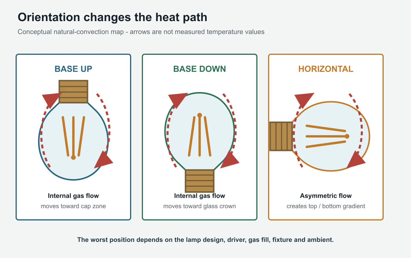
Three heat paths interact:
- Inside the bulb: the fill gas circulates around the filament structure.
- Through the glass and cap: heat conducts through materials with different geometries and thermal properties.
- Outside the bulb: ambient air moves around the envelope, fixture, shade and socket.
Orientation changes all three relationships. A horizontal lamp can also develop a top-to-bottom temperature gradient that does not appear in the same way when the bulb is vertical.
This is why a product drawing and wattage are insufficient to predict the thermal result. Filament position, gas composition and pressure, glass volume, driver topology, cap construction and fixture airflow all matter.
Concrete judgment 2
Do not declare one universal “worst orientation.” Test every position allowed by the product and required by its target fixtures, then identify the worst case for that exact model.
Why the Brightness Can Change Even When Wattage Looks Stable
LED output and efficiency are temperature-dependent. Driver behavior can also change as components warm.
In some designs, the input wattage remains close to its nominal value while stabilized lumen output changes. In others, the driver regulates differently as temperature rises. CCT or CRI movement may be small, but a strict private-label specification can still expose it.
DOE's orientation analysis is important because it did not look only at temperature. It compared input power, lumen output, CCT and CRI across positions and found that some lamp models varied.[1]
The implication is not that every difference is commercially meaningful. The implication is that buyers need two separate questions:
- Is the difference larger than laboratory uncertainty?
- Is it larger than the tolerance promised in the signed specification?
Without raw values and test conditions, a simple “PASS” cannot answer either question.
IES describes LM-79 as the recognized method for optical and electrical measurement of solid-state lighting products, and notes that test subjects are mounted and oriented under controlled conditions relevant to their use.[3] A report should therefore identify the position, voltage, ambient condition and stabilization method alongside the photometric values.
Free-Air Testing Does Not Approve a Real Fixture
A bare ceramic socket is useful because it creates a repeatable baseline. It is not the final application.
A shade can restrict external convection. A ceiling canopy can trap warm air around the cap. A narrow glass globe can reflect heat back toward the bulb. Multiple lamps in a chandelier can warm one another. Dust, ceiling cavities and local ambient temperature add further variables.
DOE purchasing guidance warns that enclosed fixtures trap heat and that heat build-up can affect LED performance and life expectancy.[4]
Orientation and enclosure therefore should not be evaluated independently. A base-up bulb in open air and the same base-up bulb inside a compact sealed globe may be two very different thermal applications.
HongYu's analysis of why G4 LED samples can fail early in enclosed fixtures explains this sample-to-application gap for compact lamps. The same procurement logic applies here: reproduce the customer fixture condition before promising life or stability.
Concrete judgment 3
A bare-socket report can establish a baseline, but it cannot approve an enclosed or airflow-restricted fixture.
Stabilization Time Is Part of the Result
Taking a measurement five minutes after switch-on may rank warm-up behavior. It may not represent stabilized operation.
Temperature continues to move until heat entering the system is balanced by heat leaving it. The required time differs by lamp shape, power, fixture and position. A large G125 globe may respond differently from a compact A60, even if both use an E27 cap.
The correct method is not to assign one arbitrary waiting time to every SKU. Monitor the relevant temperature or output until the agreed stability criterion is met, then record:
- time from switch-on;
- ambient temperature;
- voltage and frequency;
- operating position;
- fixture or bare-socket description;
- measurement location;
- stabilized input power and lumen output;
- cap, glass and internal reference temperatures when available.
For lifetime work, on/off cycling adds another dimension. The heating and cooling excursion can stress solder joints, bonding materials and driver components even when continuous operation looks stable. IES research emphasizes that LED system life depends on both application environment and use pattern, and that testing should represent the intended conditions.[5]
HongYu's guide to how long filament LED bulbs last provides the wider lifetime framework. Orientation testing adds the missing application condition to that discussion.
Concrete judgment 4
If the tracked temperature or output is still moving materially, the “steady-state” comparison is premature. Record the stabilization criterion, not only the waiting time.
A Factory Test Matrix That Answers the Right Questions
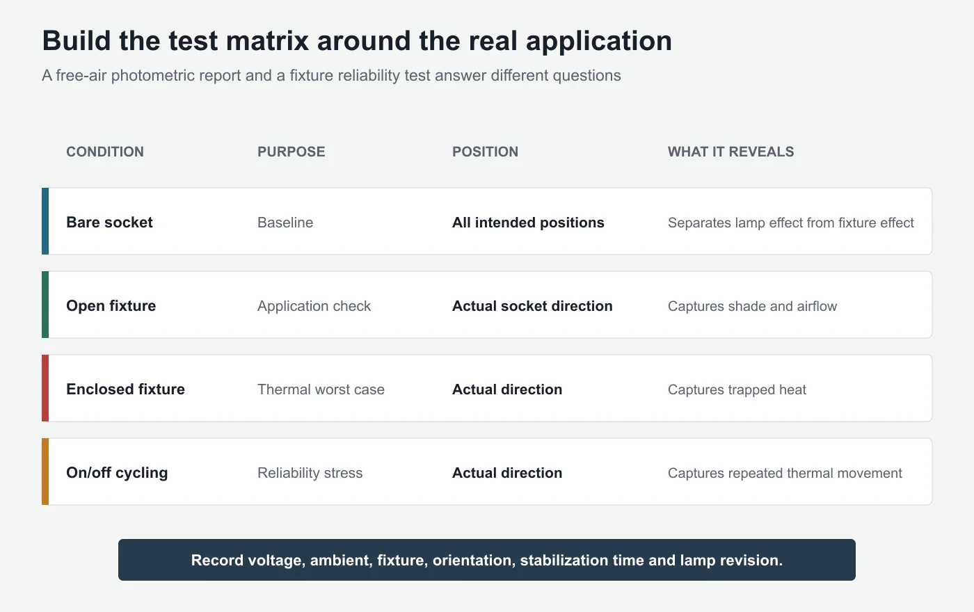
One test does not have to answer every question. A useful approval program separates screening, photometry and application reliability.
| Test stage | Position | Main purpose | Evidence retained |
|---|---|---|---|
| Bare-socket baseline | Base-up, base-down and horizontal if allowed | Identify orientation sensitivity | Raw power, lumens, CCT, CRI and temperature |
| Intended open fixture | Actual installation position | Verify shade and airflow effect | Fixture drawing, ambient and stabilized results |
| Intended enclosed fixture | Actual installation position | Identify thermal worst case | Base temperature, power behavior and protection response |
| On/off cycling | Worst measured application condition | Expose repeated thermal stress | Cycle profile, failures and drift |
| Pilot production | Same matrix on production samples | Confirm process consistency | Sample IDs, driver lot, filament lot and gas-fill record |
The buyer does not need to prescribe the laboratory's instruments in a purchase order. The buyer does need to define the application and required outputs clearly enough that two tests can be compared.
A practical request might read:
Test the approved ST64 4W E27 lamp at rated voltage in base-up, base-down and horizontal positions in a bare socket. After stabilization, report input power, lumen output, CCT, CRI, cap temperature and the defined filament or glass reference temperature. Repeat the application test base-up in the nominated pendant fixture at the agreed ambient condition.
That request is much stronger than “please provide an aging test.”
Five Buyer Checks Before Bulk Approval
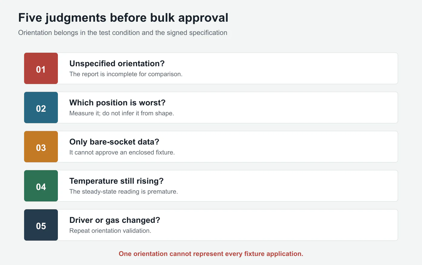
1. Confirm the allowed positions
Is the lamp unrestricted, or does the certification, datasheet or warranty limit its operating position? A restriction must appear consistently on the technical sheet, packaging and customer instructions.
2. Lock the fixture condition
Record whether the approved result came from a bare socket, open shade or enclosed luminaire. Include lamp count and spacing for multi-lamp fixtures.
3. Compare raw data, not only pass marks
A pass mark can hide a repeatable trend. Retain the actual values by orientation so the engineering team can see margin and drift.
4. Sample across production
Engineering samples assembled by hand may have ideal gas fill, filament alignment and driver components. Pull pilot and bulk samples across shifts and equipment positions.
5. Trigger revalidation after relevant changes
Changing filament construction, gas fill, driver topology, glass dimensions, cap assembly or rated power can change the thermal map even when the external appearance is identical.
These controls depend on factory traceability. HongYu's LED filament bulb factory evaluation guide explains what buyers should verify in incoming inspection, process records and engineering change control.
Concrete judgment 5
If the driver, filament, gas fill or envelope geometry changes, previous orientation approval no longer proves the revised design. Repeat the relevant validation.
What We Look for During Factory Troubleshooting
When one project reports early failures and another using the same SKU does not, replacing random components is a poor first step.
We first reconstruct the system:
- Which direction was the cap facing?
- Was the bulb open to room air or inside a shade?
- How many lamps operated together?
- What was the local ambient temperature?
- Was the lamp continuously on or frequently switched?
- Did the failed batch use the same driver, filament and gas process as the approved sample?
- Did symptoms begin as lumen loss, flicker, cycling, color shift or complete failure?
Then we test retained samples in the complaint orientation and fixture condition while monitoring temperature and electrical behavior. A control sample in a bare socket helps separate product sensitivity from fixture amplification.
This method matters because “heat problem” is not a root cause. The root cause may be insufficient driver margin, changed gas fill, poor filament placement, a fixture that traps heat or a combination that only becomes critical in one position.
The factory's job is not to prove the customer installed the lamp incorrectly. It is to determine whether the approved product specification represented the application honestly.
Conclusion
An LED filament bulb does not operate in an abstract vertical line on a datasheet. It operates cap-up, cap-down or sideways, inside a real fixture with real airflow.
Changing orientation changes natural convection and can change the thermal environment of the filaments, glass, cap and driver. Some designs may show little measurable difference. Others can show changes in power, lumen output, CCT, CRI or long-term stress. The size and direction of the effect must be measured for the actual model.
For buyers, the rule is straightforward: name the operating position, test every intended position, reproduce the target fixture, wait for a defined stabilized condition and repeat validation after thermally relevant design changes.
The same SKU in three positions is not automatically the same operating condition.
References
- U.S. Department of Energy, Proposed Test Procedure and Orientation Analysis for Integrated LED Lamps, Federal Register. ↩ first citation · ↩ second citation
- CLASP, Testing of Clear, Non-Directional LED Lamps. ↩
- Illuminating Engineering Society, Learn About IES Files and LM-79 Testing. ↩
- U.S. Department of Energy, Purchasing Energy-Efficient Light Bulbs. ↩
- Illuminating Engineering Society, Testing: Two Techniques. ↩