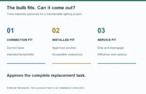
Twelve 4W LED filament bulbs add up to 48W.
The arithmetic is correct. The electrical conclusion may still be wrong.
A buyer may see a 400W wall dimmer or a 10A relay and assume that a 48W chandelier is an easy load. Yet the completed fixture can still flicker at low level, flash when switched on, buzz, fail to turn off cleanly, trip a protective device or shorten the life of the control.
The reason is that lamp wattage describes energy consumption after the lamps are operating. It does not fully describe the electrical stress seen by the switch, relay or dimmer.
An LED filament bulb contains a compact electronic driver. That driver can draw a non-sinusoidal current, charge an input capacitor at switch-on and interact with a phase-cut dimmer on every mains half-cycle. When twelve drivers operate together, the fixture is not simply one 48W resistive load. It is twelve electronic loads connected to the same control.
For lighting brands, fixture manufacturers, hospitality buyers and importers, this distinction matters because many compatibility complaints are created before the bulb is installed. The purchase specification records watts and voltage but leaves out the control type, lamp count, power factor, inrush behavior and minimum dimming condition.
This article explains what the 48W number misses, how to calculate steady-state current without overstating what the calculation proves and how to approve a multi-lamp decorative fixture before bulk production.
The First Mistake: Treating LED Watts Like Incandescent Watts
An incandescent lamp is close to a resistive load during normal operation. Its current waveform broadly follows the voltage waveform, so designers became accustomed to matching lamps and controls primarily by wattage.
An LED lamp is different.
The mains input must be converted into controlled current for the LED filaments. Even when the complete driver fits inside a small E26 or E27 base, it may include rectification, current regulation, capacitors, protection components and dimming circuitry.
The result is that at least five electrical quantities can matter:
- Real power in watts: the energy converted by the lamps during operation.
- RMS input current: the current that conductors and switching components carry in steady operation.
- Power factor: the relationship between real power and apparent power.
- Turn-on inrush current: the short current pulse when the input capacitors charge.
- Repetitive peak current: current peaks that may recur as an electronic driver operates, especially with phase-cut control.
These quantities are related, but they are not interchangeable.
Concrete judgment 1
If a multi-lamp fixture is approved using only total watts, the electrical specification is incomplete.
The total wattage remains useful. It simply answers fewer questions than many buyers assume.
What Power Factor Changes in a 12-Lamp Fixture
Power factor is the ratio of real power to apparent power. NIST expresses the relationship as real power divided by apparent power, with apparent power measured in volt-amperes.[1]
For a single-phase load, a useful relationship is:
RMS current = real power / (RMS voltage × true power factor)
Consider twelve 4W lamps. The total real power is 48W.
| Supply and true PF | Calculated RMS current for 48W |
|---|---|
| 230V, PF 1.0 | 0.209A |
| 230V, PF 0.9 | 0.232A |
| 230V, PF 0.7 | 0.298A |
| 230V, PF 0.5 | 0.417A |
| 120V, PF 1.0 | 0.400A |
| 120V, PF 0.9 | 0.444A |
| 120V, PF 0.7 | 0.571A |
| 120V, PF 0.5 | 0.800A |
These are calculations, not measurements of a specific HongYu lamp. They show why the label “48W” does not uniquely determine the RMS current.
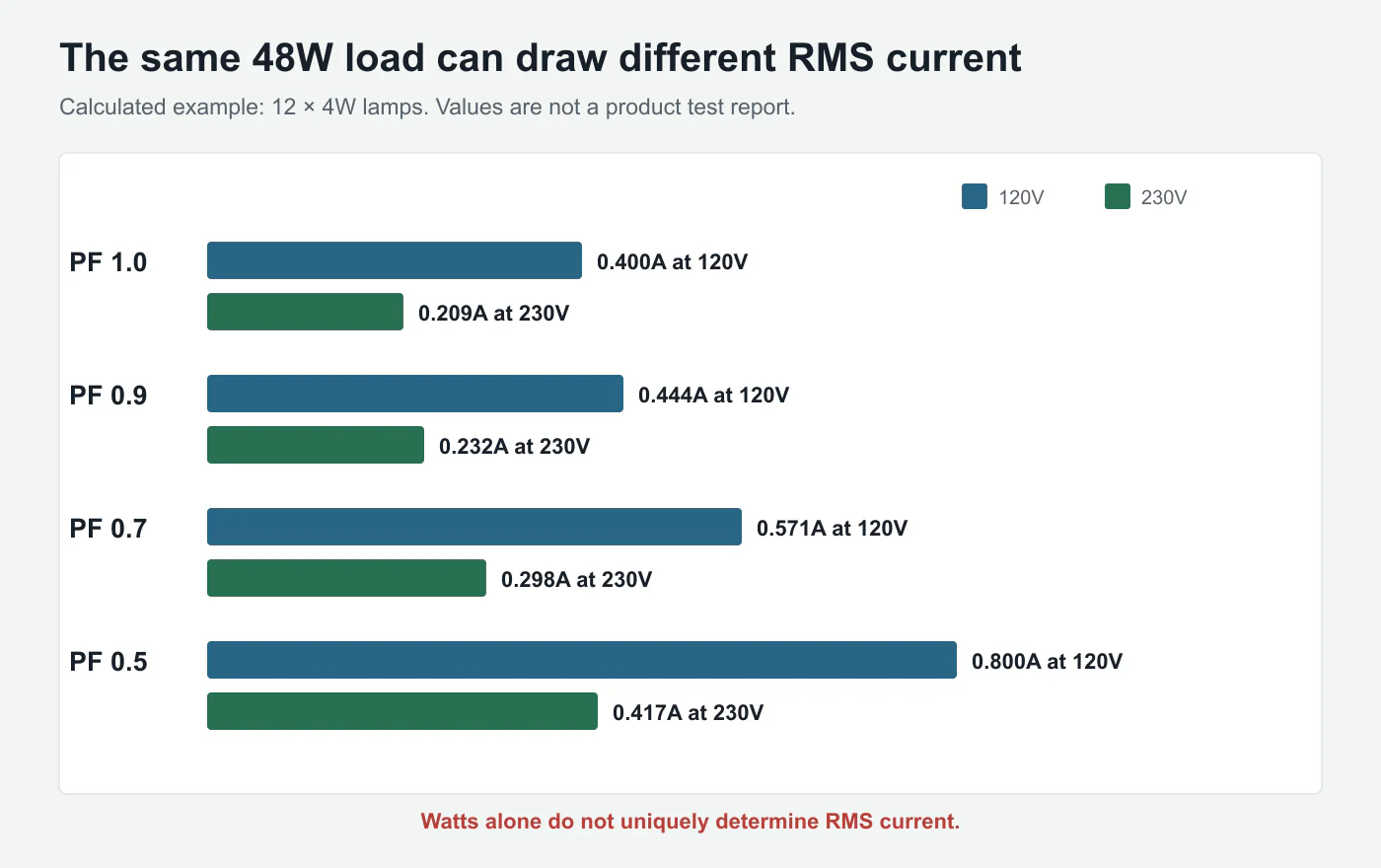
At 230V, the same 48W real-power load draws approximately twice the RMS current at PF 0.5 as it does at PF 1.0. At 120V, the current is higher again because the supply voltage is lower.
This does not mean a 48W chandelier will overload normal branch wiring. In many installations, its steady current remains modest. The important point is narrower:
A switch, relay or dimmer does not respond to the watt number printed on the carton. It responds to the actual current waveform presented at its terminals.
For importers serving both North American and European markets, voltage should therefore be treated as part of the electrical design rather than a label substitution. HongYu's guide to 110V, 220V and 100–240V LED filament bulb specifications explains why driver architecture and approval requirements change with the target supply.
Concrete judgment 2
Do not convert a dimmer's watt rating into an LED lamp count until the lamp's true PF, RMS current and the control manufacturer's LED rating are known.
An incandescent rating and an LED rating are not automatically equivalent.
True Power Factor Is More Than a Phase-Angle Number
LED drivers are non-linear electronic loads.
Their current may arrive in narrow pulses rather than as a smooth sine wave. This waveform distortion produces harmonic current. IEC 61000-3-2 addresses limits for harmonic currents injected into public low-voltage supply systems by electrical and electronic equipment, including lighting equipment under defined conditions.[2]
This creates an important terminology problem.
Some discussions use “power factor” as if it means only the cosine of the phase angle between voltage and current. That displacement value is useful for sinusoidal loads. For an LED driver with a distorted current waveform, buyers need true power factor, which includes the effect of waveform distortion.
Two lamps can consume the same watts and report a similar displacement angle while still presenting different crest factors, harmonic content and peak currents.
This is why a simple clamp-meter current reading or a generic “PF corrected” statement may not be enough for product approval. The test equipment and report should be capable of handling non-sinusoidal low-power electronic loads.
From a factory perspective, the practical questions are:
- Is PF measured on the finished lamp at rated voltage?
- Is the value recorded at full output only, or also while dimmed?
- Is input current RMS reported?
- Is current THD available for projects that require it?
- Are measurements taken after the lamp stabilizes?
- Is the same driver used in the approved sample and production order?
The goal is not to add every electrical term to every consumer box. The goal is to stop one number, watts, from carrying decisions it cannot support.
Inrush Current Is the Missing Switch-On Number
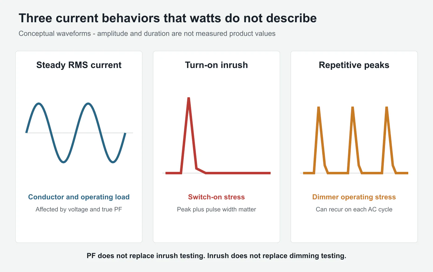
Power factor and RMS current describe steady operation. They do not describe the first instant after switching on.
Many LED drivers contain input capacitance. When power is applied, the capacitor may charge through a brief current pulse. The pulse can be many times larger than the steady-state current, although its duration is short.
When one lamp starts, the control sees one pulse. When twelve lamps are switched simultaneously, it sees the combined behavior of twelve drivers.
Signify's LED-driver design guidance defines inrush as a brief input current at connection to mains, typically with an amplitude much greater than steady-state current. It also notes that cumulative inrush from multiple drivers can cause nuisance tripping and that inrush parameters are driver-specific.[3]
The National Electrical Manufacturers Association maintains a dedicated performance-testing standard for lighting controls and switching devices used with electronic drivers and self-ballasted lamps. The existence of a separate inrush compatibility framework is itself a warning against treating electronic lighting as a purely resistive wattage load.[4]
The relevant inrush description is not only one peak-current number. Engineers may also need:
- peak amplitude
- pulse width
- test voltage and phase angle
- source impedance
- number of lamps switched together
- time between repeated switching operations
- the control's permitted LED or electronic-load rating
Without the duration and test condition, a peak value can be difficult to interpret.
Concrete judgment 3
A lamp can have acceptable steady-state watts and PF while still being a severe switching load.
PF is not a substitute for inrush testing, and inrush is not a substitute for dimming testing.
Why a Dimmer Sees More Than One Start-Up Event
A basic on/off relay mainly needs to survive turn-on behavior and continuous current. A phase-cut dimmer has a more complicated relationship with the lamp driver.
Depending on whether the system uses leading-edge or trailing-edge control, the dimmer removes part of each AC waveform. The lamp driver must repeatedly start conducting from a chopped waveform, maintain stable regulation and stop conducting in a way that allows the control to operate correctly.
This can create repetitive current peaks, not just a single pulse when the wall switch is first turned on.
Lutron's application guidance explains that LED maximum-load limits are influenced by both turn-on inrush current and repetitive peak current. It also states that the maximum number of LED lamps depends on the specific lamp model and dimming product, so testing is required rather than inferring the result from watts alone.[5]
That is why the following outcomes are all possible:
- One sample bulb dims smoothly, but twelve bulbs flicker.
- The chandelier works at 100% but drops out below 20%.
- Eleven bulbs are stable, while the twelfth pushes the system over a compatibility boundary.
- A dimmer works with one driver revision but not with a later component substitution.
- The lamps are quiet on one dimmer and buzz on another.
- The fixture operates after installation but the dimmer fails early.
HongYu's TRIAC dimming and flicker guide explains the waveform and compatibility background. For private-label orders, the more commercial question is addressed in the guide to specifying dimming compatibility before production: define the actual controller and lamp count instead of accepting “dimmable” as a complete requirement.
Concrete judgment 4
A one-lamp dimming test cannot approve a twelve-lamp chandelier.
Lamp count is part of the control system, not merely a fixture-design detail.
Minimum Load Can Fail Even When Maximum Load Looks Safe
Compatibility has a lower boundary as well as an upper one.
Legacy dimmers and no-neutral smart switches may rely on a minimum load or a small current through the lighting circuit to power their own electronics. A low-wattage LED load may not provide the expected operating condition.
The symptoms can include:
- lamps that glow faintly while switched off
- periodic flashes while off
- unstable low-end dimming
- a limited dimming range
- failure to turn on at the lowest setting
- one lamp remaining lit after others drop out
Adding more lamps may improve one minimum-load symptom while worsening inrush or repetitive peak-current stress. This is why “try another bulb” is not a complete engineering method.
HongYu's explanation of why LED Edison bulbs flash, buzz or ghost with smart switches covers leakage-current behavior in more detail.
The important specification lesson is that a fixture can be below the maximum steady wattage and still be outside the control's usable operating window.
Why Driver Size Inside the Base Matters
Decorative filament bulbs create a difficult packaging problem.
Customers want a transparent glass envelope, a small base and no visible plastic heat sink. The driver therefore has to fit into a restricted space while meeting cost, dimming, safety, EMC, flicker and lifetime requirements.
Those constraints create real trade-offs:
- Larger capacitors may improve one behavior but increase size or inrush.
- Additional filtering may reduce emissions but consume space and cost.
- Better PF correction can add components and thermal load.
- Deep dimming may require a more complex topology.
- A universal-voltage claim can require different compromises from a single-market driver.
- Component substitutions can change electrical behavior even when wattage and lumen output remain similar.
This does not mean the largest or most complex driver is automatically better. It means a buyer should approve the behavior of the complete design, not a list of isolated component claims.
When evaluating suppliers, the factory's ability to preserve an approved electrical configuration matters as much as its ability to assemble the bulb. HongYu's guide to evaluating a Chinese LED filament bulb factory explains why traceability, incoming inspection and change control affect repeat orders.
Concrete judgment 5
If a driver component changes after compatibility approval, the dimmer and multi-lamp test should be repeated.
“Same watts and lumens” does not prove the electrical load is unchanged.
A Practical Calculation That Does Not Overpromise
The 12 × 4W calculation is still useful when it is placed in the correct sequence.
Step 1: Calculate real power
Twelve lamps × 4W = 48W.
Use this for energy consumption, thermal planning and an initial control screen.
Step 2: Estimate RMS current using true PF
At 230V and PF 0.7:
48W / (230V × 0.7) = approximately 0.298A.
At 120V and the same PF:
48W / (120V × 0.7) = approximately 0.571A.
This estimates steady RMS current. It does not predict the current waveform or inrush.
Step 3: Apply the control's LED-specific rating
Do not use an incandescent watt rating unless the manufacturer explicitly permits that interpretation for the intended LED load.
Step 4: Check the tested lamp count
The most useful compatibility statement is specific:
Lamp model + driver revision + supply voltage + control model + number of lamps + tested dimming range.
“Works with TRIAC dimmers” is not equivalent.
Step 5: Validate in the complete fixture
Wiring length, switch type, neutral availability, fixture temperature and the number of simultaneously connected lamps can affect the outcome.
The calculation filters obviously unsuitable combinations. The complete-system test approves the product.
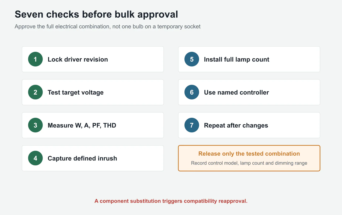
Seven Factory Checks Before Bulk Approval
1. Lock the lamp and driver revision
Record the lamp model, driver board version and critical electrical components used in the approved sample.
2. Test at the target supply
Use the actual market voltage and frequency. A 120V result should not be silently extended to 230V, or vice versa.
3. Measure the finished lamp
Record watts, RMS current, true PF and, where required, current THD after stabilization.
4. Capture inrush under a defined method
Record peak current, pulse duration and test conditions. Avoid presenting one unexplained peak number as a universal product property.
5. Install the intended lamp count
Test one lamp for diagnosis, then test the full fixture count for approval.
6. Use the named control
Record the exact dimmer, relay, smart switch or sensor model. Test minimum and maximum settings, repeated switching and warm restart.
7. Repeat after any electrical change
Re-test when the driver topology, capacitor, controller IC, switching component or critical supplier changes.
This process is more valuable than collecting a long generic compatibility list that does not record voltage, lamp count or driver revision.
What Buyers Should Put in the Purchase Specification
A stronger chandelier or multi-lamp bulb specification should include:
- lamp model and driver revision
- rated voltage and frequency
- input watts per lamp
- RMS input current
- true power factor
- current THD where required
- dimmable or non-dimmable configuration
- control brand and model
- leading-edge, trailing-edge or other control method
- intended number of lamps per circuit
- required minimum stable dimming level
- off-state glow requirement
- inrush test method and result where switching capacity matters
- warm-start and repeated-switching test
- change-control and reapproval requirement
Certification remains a separate question. A safety or EMC mark does not automatically prove smooth operation with every dimmer. HongYu's ETL, CE and RoHS sourcing guide explains what those documents cover and what still requires project-level verification.
The best specification does not demand impressive numbers without context. It connects each measurement to a failure mode the project needs to prevent.
The Manufacturer's View: Compatibility Belongs to the System
From a factory perspective, “the bulb flickers” is often an incomplete diagnosis.
The lamp may be unstable with one control and smooth with another. The same dimmer may work with four lamps and fail with twelve. A smart switch may need a neutral connection or bypass device. A component change may alter the current waveform without changing the carton label.
This does not remove the manufacturer's responsibility. It defines it more accurately.
A responsible lamp supplier should provide stable driver construction, honest electrical data and compatibility testing. A responsible fixture buyer should provide the target voltage, control model and full lamp count. The fixture brand should retain the approved combination and re-test changes.
The useful unit of approval is therefore not the bulb alone.
It is:
bulb + driver revision + voltage + control + lamp count + wiring condition.
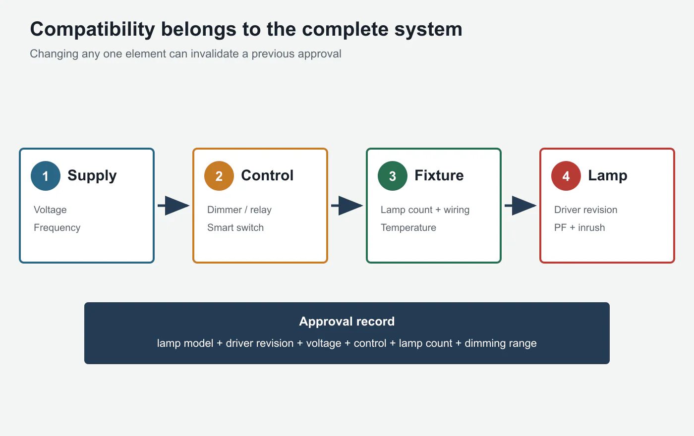
That system view prevents the most expensive kind of compatibility failure: one that appears only after hundreds of fixtures have been installed.
Conclusion
Twelve 4W LED filament bulbs do consume 48W of real power. But 48W does not fully describe the load seen by a dimmer, relay or smart switch.
True power factor changes the RMS current required to deliver those watts. Harmonic distortion changes the waveform. Input capacitors create turn-on inrush. Phase-cut control can create repetitive current peaks. Minimum-load and leakage requirements can destabilize a system even when the maximum wattage appears safe.
The practical rule is simple:
Use watts to estimate energy. Use electrical measurements and a complete-fixture test to approve compatibility.
Before a multi-lamp decorative fixture enters production, record the finished-lamp current, true PF, inrush condition, exact controller and full lamp count. Test the useful dimming range, off-state behavior and repeated switching. Repeat the test if the driver changes.
The sharpest buyer question is not:
“Is 48W below the dimmer rating?”
It is:
“Has this exact 48W electronic load been tested on this control with all twelve lamps connected?”
References
- National Institute of Standards and Technology, NIST SP 1900-601 ↩
- International Electrotechnical Commission, IEC 61000-3-2 ↩
- Signify, Xitanium LED Driver Design-in Guide ↩
- National Electrical Manufacturers Association, Electrical Standards and Products Guide: NEMA 410 ↩
- Lutron, Application Note 487: Minimum and Maximum Loads for LED and CFL Lamps and Fixtures ↩